Monday, May 26, 2014

The invisible cure: Using UV activated glue for vent window catches

One of the problems many Dino owners struggle with is properly bonding the metal catches on the front vent windows. Knowing this to be a problem we investigated a number of adhesives that would offer a reliable bond. Sticking metal to glass is never something that is easy and on the vent windows things are further complicated as the glue join is under quite a bit of tension from the spring effects of the molding rubber that surrounds the vent window. In the end the solution came from our neighbor Joe who offered us a high strength adhesive made by Loctite and cured using the invisible powers of UV light. He supplied us with the glue, curing lamp, and requisite yellow safety glasses (that make our Dino disappear)


Before trusting the glue on the car we ran a test using a scrap piece of glass and an extra mount we had. The cool thing about the adhesive is that it cures in about 90 seconds.


Once dry we administered the most un-sophisticated durability test we could muster. With the glass held in a vise we hammered and hammered until the bond or the glass broke. In the end neither failed as we just could not grip the thick piece of glass we had tight enough to keep it from moving however with the metal mount deforming and starting to bend we were pretty sure we had the glue for the job.


Now for the real thing. We carefully located the mount on the vent window using a black piece of decal material with a perfect hole cut in it. The decal served 2 purposes. One is that it really helped locate the pin well and second because no light goes through it, all of the overflow glue stays fully liquid making for a perfect masking. When the light is turned off all you need to do is pull the decal away and there is no mess or leakage to clean up. To be honest we tripped over the second benefit totally by accident but it was very welcome and a tip worth sharing.


Lastly here is the finished assembly. Ignoring that everything is covered in fingerprints and could use a proper cleaning, another job is removed off of the list :)

Saturday, May 24, 2014

Path of least resistance: Wiring harness restoration Part 3

In the last few posts we have been reviewing the wiring harness restoration. The harness is now finished and ready to go in.


The first step to getting the harness in is establishing its general path into the car and then preparing it for fitting. In the photo below Paul looks eager to get to work and to speed things along we put the bulk of the harness on a rolling cart. It of course goes without saying that we covered the paint very carefully to avoid any damage.


On the Dino the bulk of the harness enters on the drivers side just under the windshield wiper motor


Below you can see the wires once they passed through the front bulkhead and are now ready to feed through the car.


Some of the wires stay in the passenger cabin while others pass along just under the surface of the dashboard.


While most of the wires are concentrated in the front half of the car there are still some wires that need to go to the back to run the ignition, tail lights, and other electrical items. These wires exit the under dash area on the passenger side, run down the front wheel arch and along the main side chassis tube back to the rear of the car. In order to keep these wires clean and to help feed them quickly we wrapped them in plastic. This make quick work of fitting the harness.


In the end while we have lamented about some terrible jobs on this car, however with the task being done early in the build, the wiring installation went rather smoothly. Rough running of the wires tool about 30 minutes while final positioning and checking well lets say took rather more time.


Wednesday, May 21, 2014

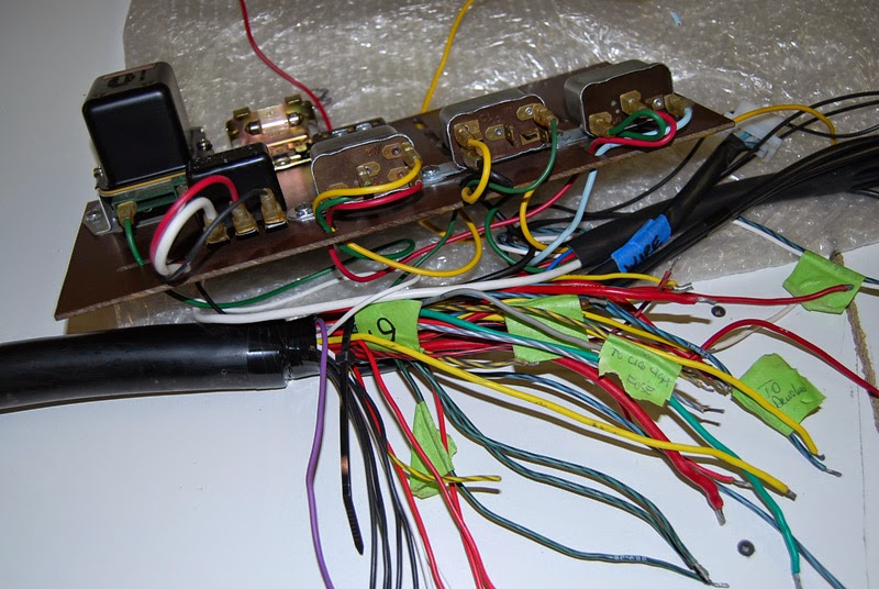
Wires wires everywhere: Wiring harness restoration Part 2

In our last post we introduced our task of restoring the original wiring harness. As noted the first step was to map out the entire harness tracing each individual wire to its corresponding circuit. With this job done we could now turn our attention to the actual restoration of the harness which can be broken down in 4 separate steps:

1. Remove and restore all the wire terminal insulators
2. Replace all plastic sheathing on wires and add new wire ends
3. Attach harness to fuse panel
4. Test the assembly

Now we shall cover the various steps:

1. Remove and restore all the wire terminal insulators

One part that is not available anywhere are replacements for the original wire ends. Molded in soft clear plastic they carry the word ITALY on them and are a nice original detail. We were lucky to have ours in pretty nice shape and after a few hours of cleaning and scrubbing got them to the point where they were looking quite good.


2. Replace all plastic sheathing on wires and add new wire ends

This one was the big one. The entire harness is covered with a black plastic sheathing to protect the wires from abrasion. Over time this material hardens and looses its flexibility. The big challenge comes in looking at the harness as a whole and figuring out the order to replace the sheathing as the whole assembly is like a big jigsaw puzzle with no instructions. Generally you work from larger diameter to smaller but the harness can get pretty complicated and I found the only solution was to break the harness down into smaller sections. Each section was then identified, photographed, and then drawn on a piece of paper with notes showing the location of breaks and electrical tape.

Because each section feeds into the next the photos and drawings become critical because ALL of the sheathing on the entire harness needs to be removed in order to be able to replace it. No matter how good your memory is, over the several days this job takes, the reference drawings are essential to getting things right.


With all of the wire re-covered it is now time to put new wire ends on. Originally the wire ends from Ferrari were tinned and have a silver colour (reproduction harnesses are generally gold in colour). We sourced the correct wire ends and bought the right crimping tool to perfectly match the original crimps. This matched to the restored plastic ends gave us wires that looked factory fresh.


3. Attach harness to fuse panel
 
As previously reported our fuse panel had been replaced leaving us to make a new one from scratch. As such we had no data on which to figure out the connections to the panel. This easily ate up 10 times the work as it should have because simple connections turned into elaborate testing procedures before running power to the panel. In the end though we were really pleased that everything turned out well.


4. Test the assembly
 
Despite all the time we spent trying to get things perfect you never know until you test the assembly. Invariably something goes wrong and when things got sticky for us our friend Myron S. came by the shop to help us along. Myron is a professional electrical engineer and his input was invaluable to getting our electrics working well. We owe him a debt of gratitude for taking time out of his Saturday to come and help us out.
 
In all the electrical harness took over 2.5 weeks of solid work to get right. It was much more involved than I ever imagined but the result is a 40 year old assembly that looks like it was made yesterday. Our next installment shows the harness going in.

Monday, May 19, 2014

The long table: Wiring harness restoration Part 1

In previous blog installments we discussed how our car had the incorrect fuse panel fitted to it at some time in its life. As such we needed to source, restore, and (when unavailable) manufacture the missing components needed to replicate a new one. Some of the posts on this subject are here:

http://dino246blog.blogspot.ca/2011/12/little-help-from-sweeden-fuse-panel-is.html

http://dino246blog.blogspot.ca/2013/05/121-gigawatts-finishing-fuse-panel.html

http://dino246blog.blogspot.ca/2013/01/a-faint-rectangle-helps-dino-restorers.html

http://dino246blog.blogspot.ca/2013/12/original-vs-replacement-difference-in.html

With the fuse panel completed it was now on to the daunting task of restoring our wiring harness. In most instances the fastest and easiest route would be to buy a replacement harness however, in our case, certain nice original details of our harness allowed us to justify the massive extra work involved in restoring rather than replacing:

- Our original harness was still supple and the plastic on the wires had not dried out with time

- Despite 3 colour changes over the decades our harness had no paint overspray on it which is almost impossible to properly remove.

- The original harness has markings in Italian on them denoting the task of the individual wires. This in addition to wire colours that are not replicated with the reproduction harness' made keeping the original an easier decision.

- Reproduction wiring harnesses have different wire ends to original making them an immediate giveaway to the knowledgeable observer

With the decision to restore the process all started with getting the old and dirty wiring harness out of storage.


The next step was to lay everything out on a LONG table where the entire harness would be compared to period photos and the original wiring diagrams to ensure that everything is correct. Despite the few circuits involved this job took many days of concentrated effort to get right.


By this stage the harness has most of its cables identified. Once this is done each cable is tested for continuity and resistance to make sure that there are no unexpected problems. Inevitably a few bad wires are found and they are carefully removed whole and replaced. Where we got very lucky is that all of the bad wires were easy to replace colours rather than some of the more strange striped wires that the harness has for some of its circuits.


With the harness all mapped out the next step is full on restoration which we will cover in our next post. Stay tuned.


Thursday, May 15, 2014

The Lone Stallion: Installing the factory ID plate

Way back at the beginning of this blog we showed how the original chassis number was unearthed hidden under layers of paint. Here is the link for those who do not remember the post:

http://dino246blog.blogspot.ca/2010/10/unearthing-identity.html

Back in the day the Dino was seen as a poor mans Ferrari so it was common for owners and even dealers to fit Ferrari badges and horses all over the body and interior. As Dino's have begun to be appreciated as their own sub-brand, restorers have shed the non-original badges leaving only the factory installed Dino markings.

That said there is one Ferrari horse that is totally correct to original and the only Ferrari emblem that appears on the whole car. This is located on a small aluminum plate that is pop riveted to the panel that separates the engine bay from the trunk. Ours was totally original and in excellent condition so it got little more than a quick wipe with a cloth before installing it on the freshly restored panel.

This job was left to Paul and Dad who appear to be relieved to have had such a simple job go smoothly. If only all the tasks could be this easy.