In our last post we introduced our task of restoring the original wiring harness. As noted the first step was to map out the entire harness tracing each individual wire to its corresponding circuit. With this job done we could now turn our attention to the actual restoration of the harness which can be broken down in 4 separate steps:
1. Remove and restore all the wire terminal insulators
2. Replace all plastic sheathing on wires and add new wire ends
3. Attach harness to fuse panel
4. Test the assembly
Now we shall cover the various steps:
1. Remove and restore all the wire terminal insulators
One part that is not available anywhere are replacements for the original wire ends. Molded in soft clear plastic they carry the word ITALY on them and are a nice original detail. We were lucky to have ours in pretty nice shape and after a few hours of cleaning and scrubbing got them to the point where they were looking quite good.
2. Replace all plastic sheathing on wires and add new wire ends
This one was the big one. The entire harness is covered with a black plastic sheathing to protect the wires from abrasion. Over time this material hardens and looses its flexibility. The big challenge comes in looking at the harness as a whole and figuring out the order to replace the sheathing as the whole assembly is like a big jigsaw puzzle with no instructions. Generally you work from larger diameter to smaller but the harness can get pretty complicated and I found the only solution was to break the harness down into smaller sections. Each section was then identified, photographed, and then drawn on a piece of paper with notes showing the location of breaks and electrical tape.
Because each section feeds into the next the photos and drawings become critical because ALL of the sheathing on the entire harness needs to be removed in order to be able to replace it. No matter how good your memory is, over the several days this job takes, the reference drawings are essential to getting things right.
With all of the wire re-covered it is now time to put new wire ends on. Originally the wire ends from Ferrari were tinned and have a silver colour (reproduction harnesses are generally gold in colour). We sourced the correct wire ends and bought the right crimping tool to perfectly match the original crimps. This matched to the restored plastic ends gave us wires that looked factory fresh.
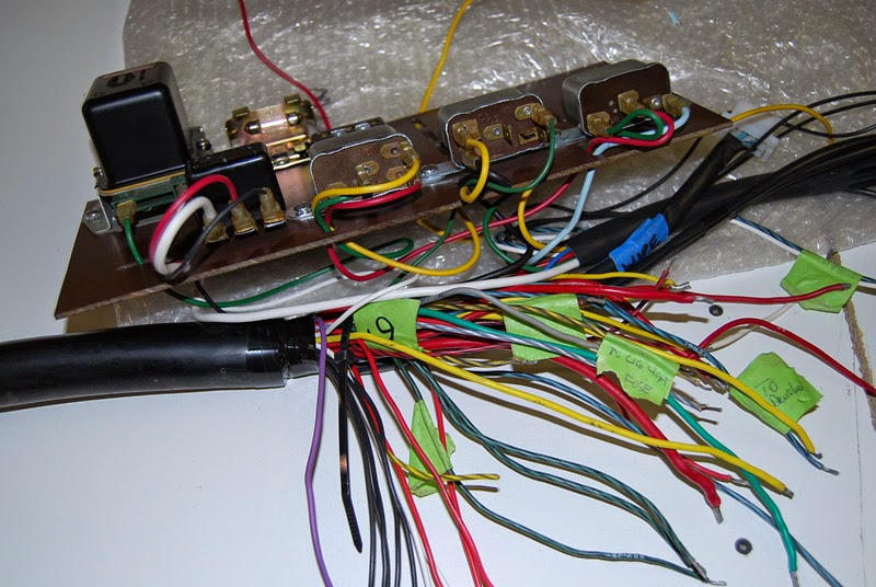
3. Attach harness to fuse panel
As previously reported our fuse panel had been replaced leaving us to make a new one from scratch. As such we had no data on which to figure out the connections to the panel. This easily ate up 10 times the work as it should have because simple connections turned into elaborate testing procedures before running power to the panel. In the end though we were really pleased that everything turned out well.
4. Test the assembly
Despite all the time we spent trying to get things perfect you never know until you test the assembly. Invariably something goes wrong and when things got sticky for us our friend Myron S. came by the shop to help us along. Myron is a professional electrical engineer and his input was invaluable to getting our electrics working well. We owe him a debt of gratitude for taking time out of his Saturday to come and help us out.
In all the electrical harness took over 2.5 weeks of solid work to get right. It was much more involved than I ever imagined but the result is a 40 year old assembly that looks like it was made yesterday. Our next installment shows the harness going in.